Station Setup
The station has several core components:
- The control computer
- The spectrometer (and associated optics)
- Power control
- The motor
- GPS (for time keeping)
This section will describe the setup and operation of each of these components in the OpenSO2 scanner. All instructions are up to date at the time of writing (November 2019), but please check with the individual sources for more up-to-date installation instructions.
Note
The details below refer to specific components as these are the components with which the OpenSO2 scanner was developed. These are not the only solutions available, so the station software is designed to be modular so that the specific components used can be changed with relative ease.
The Control Computer
The OpenSO2 software has been designed to work on a Raspberry Pi single board computer. This controls the different components and analyses the collected data in real time. The Raspberry Pi only stores the data, the home station is responsible for retrieving the data from the Pi. Beyond the additions detailed here a small heatsink was added to the Rasberry Pi in order to assist with the termal regulation of the CPU.
Operating System
The OpenSO2 software was designed using the Raspbian operating system. To ensure full functionality the user should flash the Raspbian image (available from <https://www.raspberrypi.org/downloads/>_) directly onto the SD card. Do not use the NOOBS installer as this causes some issues with the WittyPi2 power control board (see below).
Spectrometer
The OpenSO2 station is designed to work with an Ocean Optics spectrometer. The spectrometer is controlled through a Python library called Python Seabreeze, which is maintained on GitHub here .
The spectrometer is connected to the Raspberry Pi by a USB cable which provides power and control.
To install the library with pip:
pip3 install seabreeze
seabreeze_os_setup
The second command installed the UDEV rules allowing control of the spectrometer. You may have you re-open the terminal to run the second command.
Power Control
To reduce power consumption the station enters a “low power” mode when not collecting data and turns off completely overnight. The control of the power is achieved using the WittyPi2 board which incorporates a Real Time Clock (RTC) to allow the Raspberry Pi to maintain the correct time when shutdown and program the Pi to automatically turn itself back on again.
To install the required software use the following commands from the home directory:
wget http://www.uugear.com/repo/WittyPi2/installWittyPi.sh
sudo sh installWittyPi.sh
Note
It is strongly suggested that this is done before mounting the WittyPi2 board
This script goes through several steps to ensure the WittyPi2 board will operate correctly. Note it is not necessary to install Qt as we will not be using the GUI.
The power on and off times are controlled through a schedule file. In the /home/pi/wittyPi folder create a text document called schedule.wpi containing the following text:
BEGIN 2018-01-01 06:00:00
END   2050-01-01 23:59:59
ON    H12
OFF   H12
This script tells the wittyPi board to turn the Pi on from 6:00 to 18:00 everyday. This time is UTC, so the BEGIN time will require adjusting for the local time zone. The script is then activated by running:
sudo ./run_script.sh
This will summerise the timing details so they can be checked.
Note
There is an issue with using the WittyPi software when using Raspian with NOOBS. Details on how to work around this can be found in the WittyPi2 user manual, however they do not seem to work for the latest versions of NOOBS. Please avoid this issue by directly flashing the OS to the SD card.
To allow the OpenSO2 software to update the RTC time on the WittyPi2 board place the system_to_rtc.sh file in the wittyPi folder. Make sure it is executeable with chmod +x system_to_rtc.sh
Scanner Head
The scanner head is rotated using a stepper motor controlled by the Raspberry Pi. The motor requires a separate control board to operate with a separate power supply.
The OpenSO2 scanner uses a board called the Adafruit Motor HAT. to control the stepper motor. Details can be found in the Adafruit documentation. To operate the HAT Adafruit Blinka must first be installed:
pip3 install -upgrade setuptools
Next enable I2C and SPI and reboot. Then run the following commands:
pip3 install RPI.GPIO
pip3 install adafruit-blinka
Then install the circuit python library for motor control:
pip3 install adafruit-circuitpython-motorkit
The motor control should now work.
To ensure that the angular accuracy of the stepper motor does not drift with time a microswitch is used to “home” the scanner head after each rotation. The switch should connect to one of the GPIO pins of the Raspberry Pi (accessible on the Motor-HAT). The default is pin 21.
GPS
To obtain the GPS information requires the GPS module in python as well as GSPD to talk to the GPS device. To install these run:
sudo apt-get install gpsd gpsd-clients
pip3 install gps
OpenSO2 also changes the RTC time of the wittyPi board to make sure that the board time matches the system time of the Pi when connected to the GPS.
You should also check that the time zone for the Pi is set to UTC by running:
sudo dpkg-reconfigure tzdata
selecting None of the above and setting the TimeZone to UTC.
Communication
The OpenSO2 software requires a local network connection between the stations and the home computer. This is achieved through an ethernet connection on the Raspberry Pi computer.
Wiring
The figure below shows how the various components of the OpenSO2 scanner are connected. Note that the boards are stacked on top of each other.
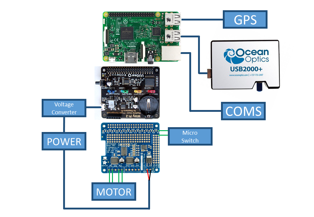
Basic wiring layout for the OpenSO2 scanner station.
The station is designed to run off a 12V power supply. This power is split between the motor HAT and the Raspberry Pi. The Pi requires a voltage converter to reduce the voltage to safe levels.
Note
The power to the Raspberry Pi is connected through the Micro USB connection on the WittyPi2 board, not through the usual Raspberry Pi connection. This allows the WittyPi2 board to modulate the power to the Pi.
The scanner head requires connections for both the stepper motor and the microswitch. The stepper motor should be connected to the left hand motor ports on the Motor-HAT. The order of these connections is important, and more information about finding the correct wiring can be found on the Adafruit Motor-HAT website. The microswitch should be connected to the GPIO pin 21 (and ground).
Note
If using an optical microswitch then additional wiring is required to power the LED from the 5V rail (with an 100 Ohm resistor).
Both the spectrometer and GPS are simply connected to the USB slots, and the ethernet cable for connection to the local network is plugged into the ethernet slot.
Startup Script
A startup script is needed to tell the Raspberry Pi to run the station software when it boots. Firstly make sure that the script run_scanner.py is executable by navigating to the open_so2/ folder and running:
chmod +x run_scanner.py
Now to run it on startup add the following lines to the startup script /etc/rc.local above the exit 0 line:
sudo systemctl stop gpsd.socket
sudo systemctl disable gpsd.socket
sudo gpsd /dev/ttyUSB0 -F /var/run/gpsd.sock

cd /home/pi/open_so2/
sudo /home/pi/open_so2/./run_scanner.py &
Warning
The & symbol is essential, otherwise the Raspberry Pi will be stuck in an infinite loop on startup. This is very difficult to fix without fully reinstalling the Operating System!
This script does two things:
- Starts the GPS running
- Launches the station software
To test reboot the Raspberry Pi and the software should create a Results folder and log file for that day.